FREQUENCY RESPONSE
By comparing the simulation results with the
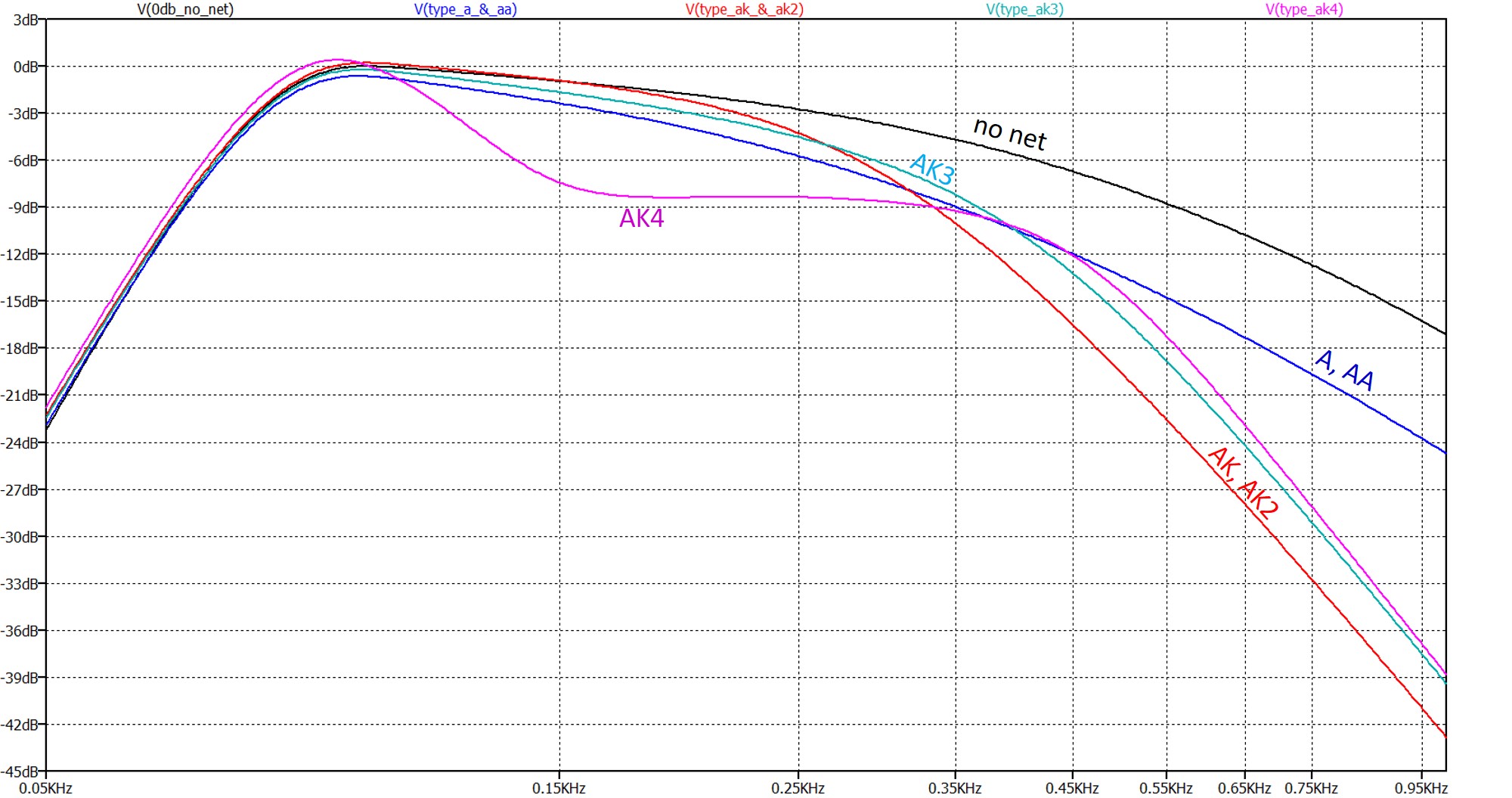
"no net" horn response, the design intent of each network can be proposed.
When compared to the no net response, the simple first order networks A and AA
provide about 6dB of attenuation at the 400Hz crossover frequency used in the
system. Above that frequency, the effective attenuation (horn and
network) is about 50dB/oct.
The AK and AK2 nets provide output consistent with the A and AA over the pass-band of the filter but enhance attenuation above the pass-band which, based on the simulation, is about 90dB/oct.
The AK3 appears to be a minor revision that increases 400Hz output by 3dB with an attenuation above 400Hz consistent with the AK and AK2 nets.
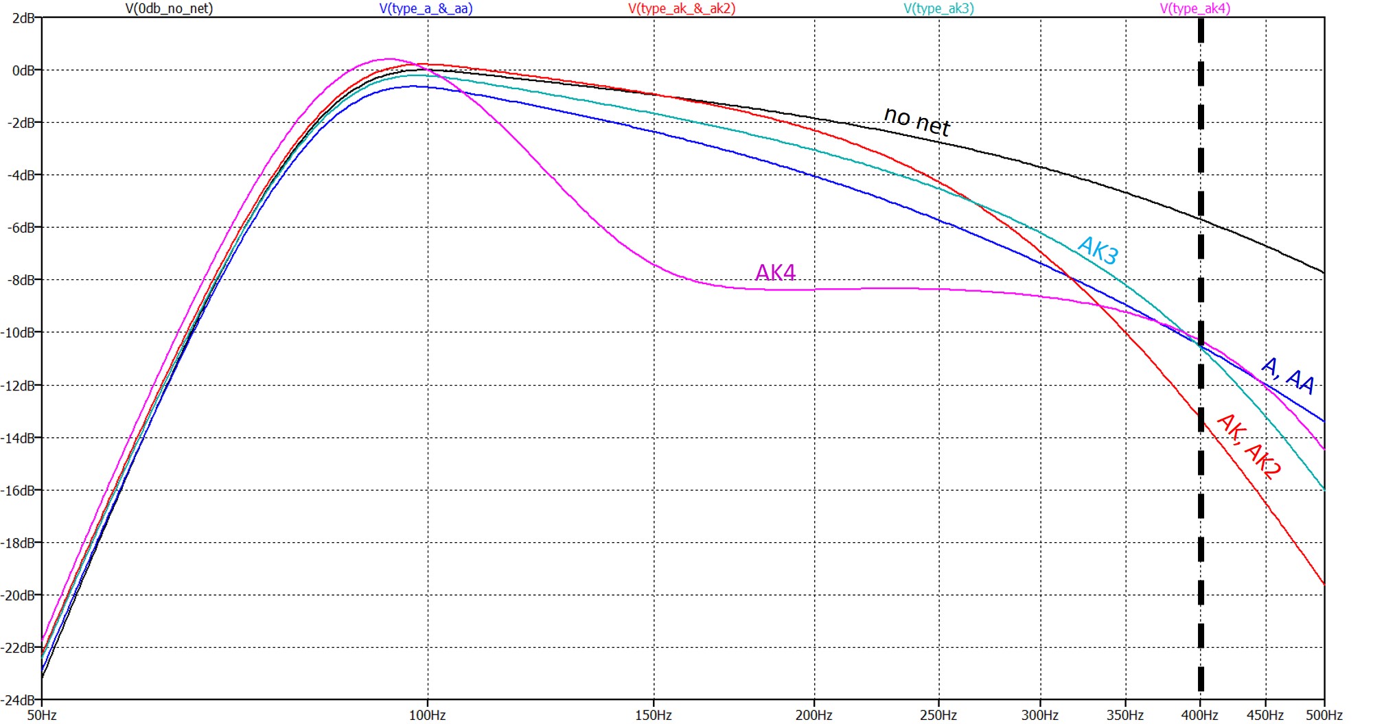
The AK4 is a significant departure from earlier designs and provides pass-band frequency contouring via notch-filtering over the range of frequencies where the horn sensitivity demonstrates a maximum, i.e. between 100-300Hz. The result is a somewhat smoother acoustic response with concomitant reduction in sensitivity. The attenuation above 400Hz is the same as the AK3.
Plot below is same simulation as above but showing responses between 50 and 500Hz. 400Hz crossover frequency to the midrange horn is highlighted.
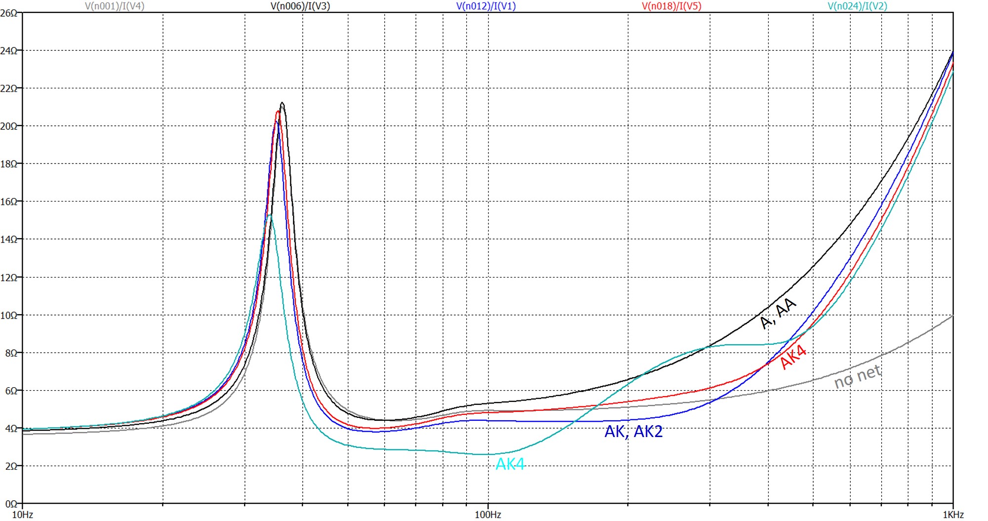
IMPEDANCE MAGNITUDE
The magnitude of the complex impedance of the horn-network combinations is
simulated and plotted below. A 4Ohm minimum impedance magnitude is seen in
all networks expect the AK4 where the effect of the notch filter lowers the
minimum to near 2.6Ohm. For some amplifiers this might prove difficult to
drive thus prompting the factory to revise the design to the current production
AK5 filter (not modeled).
The voice coil resistance, Re, is 3.5Ohms. As is evidenced below, the minimum impedance magnitude is higher and attributed to horn loading which increases the resistance seen by the voltage source. The resistance increase is associated with the radiation resistance of the horn, Ret, reflected back to the voltage source terminals thru the K33E motor assembly. Note however that the addition of complex conjugate element (i.e. notch filter) can alter, quite significantly, the impedance magnitude measured in the system.
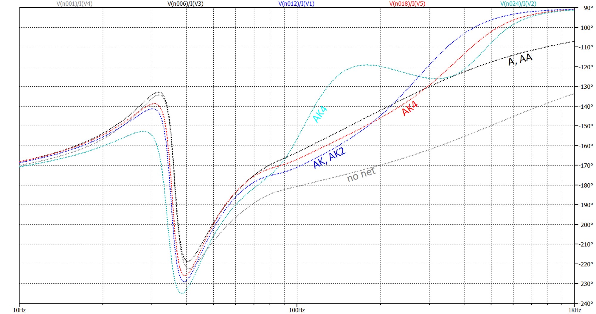
PHASE RESPONSE
The phase angle over the range of frequencies
modeled is shown below for the horn-network combinations considered in this
analysis.
Webpage content property of John Warren of North Reading Engineering, North Reading, MA 01864 USA. No part of the above work may be copied and published, in part or in total, without written permission. © 2018 John Warren